Frac stacks are high-pressure wellhead assemblies used to control and direct hydraulic fracturing fluid into a wellbore — and they are the single most important piece of pressure-control equipment during any fracking operation.
In the oil and gas industry, the success and safety of a hydraulic fracturing job depend heavily on the integrity of surface equipment. Among all the components involved, frac stacks stand out as indispensable. Whether you are an engineer evaluating completion equipment or a procurement specialist comparing pressure-rated assemblies, understanding frac stacks — their design, function, ratings, and selection criteria — is essential.
This guide provides a comprehensive look at frac stacks: what they are, how they work, how they differ from traditional wellhead equipment, and what factors determine which frac stack configuration is right for a given well.
Content
- What Is a Frac Stack?
- How Does a Frac Stack Work During a Hydraulic Fracturing Job?
- Frac Stack vs. Traditional Wellhead: Key Differences
- Frac Stack Pressure Ratings: What Do They Mean?
- Key Components of a Frac Stack Assembly
- Types of Frac Stacks: Single, Double, and Zipper Configurations
- Material Selection and Wear Resistance in Frac Stacks
- API Standards Governing Frac Stack Design and Testing
- How to Select the Right Frac Stack: A Practical Checklist
- Frac Stack Maintenance, Inspection, and Service Life
- Innovations in Frac Stack Technology
- Frequently Asked Questions About Frac Stacks
- Conclusion: Why Getting Frac Stacks Right Matters
What Is a Frac Stack?
A frac stack is a specialized wellhead pressure-control assembly installed at the surface of an oil or gas well specifically for hydraulic fracturing operations. Unlike a standard wellhead, which is designed for long-term production, a frac stack is engineered to withstand the extreme pressures and abrasive slurries associated with pumping fracturing fluid — often a mixture of water, proppant, and chemical additives — deep into the formation.
At its core, a frac stack typically consists of:
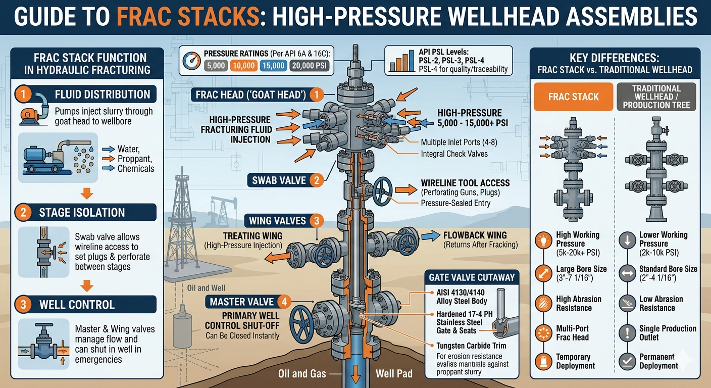
- A master valve — the primary shut-off valve at the base of the stack
- A swab valve — allows wellbore access for wireline tools
- Wing valves — direct flow to and from fracturing lines
- A frac head (or goat head) — the top manifold connecting multiple treating iron lines
- Check valves and kill lines — for well control and emergency pressure relief
Together, these components allow crews to pump fracturing fluid at extremely high pressures — typically between 5,000 and 15,000 PSI, though ultra-high-pressure applications can exceed 20,000 PSI — with precision and safety.
How Does a Frac Stack Work During a Hydraulic Fracturing Job?
A frac stack acts as the primary interface between high-pressure surface pumping equipment and the wellbore, controlling fluid injection throughout every stage of the fracturing program.
When a hydraulic fracturing job begins, high-pressure pumps force fracturing fluid through treating iron lines that connect to the frac head. The frac head — often called a "goat head" due to its multi-port configuration — distributes fluid from multiple pump trucks simultaneously into the wellbore. This allows operators to achieve the extremely high injection rates (sometimes exceeding 100 barrels per minute) required to fracture tight formations.
Throughout the operation:
- The master valve can be closed instantly to shut in the well in an emergency
- Wing valves are opened or closed to manage flowback and treating lines
- The swab valve enables re-entry with wireline tools between stages
- Kill lines allow operators to pump kill fluid to regain well control if needed
After fracturing is complete, the frac stack may be removed and replaced with a production tree, or it may remain temporarily during flowback operations.
Frac Stack vs. Traditional Wellhead: Key Differences
Frac stacks and conventional wellhead assemblies serve different purposes and are built to different standards. The table below summarizes the critical distinctions.
| Feature | Frac Stack | Traditional Wellhead / Production Tree |
| Primary Purpose | Hydraulic fracturing fluid injection | Long-term production control |
| Working Pressure | 5,000 – 20,000+ PSI | 2,000 – 10,000 PSI (typical) |
| Bore Size | 3" – 7-1/16" (large bore preferred) | 2" – 4-1/16" (standard) |
| Abrasion Resistance | High — designed for proppant slurry | Low — not designed for abrasives |
| Multi-Port Frac Head | Yes — multiple pump connections | No |
| Deployment Duration | Temporary (days to weeks) | Permanent (years to decades) |
| API Standard | API 6A / API 16C | API 6A |
Table 1: Comparison between frac stacks and traditional wellhead/production tree assemblies across key operational parameters.
Frac Stack Pressure Ratings: What Do They Mean?
Pressure rating is the single most important specification when selecting a frac stack — it directly determines whether the assembly can safely contain wellbore and treating pressures.
Frac stacks are pressure-rated per API 6A and API 16C standards. Common working pressure (WP) classes include:
- 5,000 PSI WP — suitable for lower-pressure, shallower formations
- 10,000 PSI WP — the most widely deployed rating in major U.S. shale plays
- 15,000 PSI WP — used in deep, high-pressure wells such as the Permian Basin's deeper targets
- 20,000 PSI WP — emerging class for ultra-deep or ultra-tight formations requiring extreme treating pressures
It is critical to note that the working pressure rating of the frac stack must equal or exceed the maximum anticipated surface treating pressure (MASITP) for the job, including a safety margin. Operators typically apply a 10–15% safety margin above the calculated MASITP when selecting frac stack pressure ratings.
A mismatch — using an under-rated frac stack — can result in catastrophic blowout or equipment failure. According to industry analysis, pressure-related wellhead incidents remain one of the top causes of serious injury during completion operations, underscoring why proper rating selection is non-negotiable.
Key Components of a Frac Stack Assembly
Each component within a frac stack plays a specific role in maintaining well control and directing fracturing fluid.
1. Master Valve
The master valve is the first line of defense in well control — it can completely shut in the wellbore with a single operation. Typically a full-bore gate valve, it is installed directly above the casing spool or wellhead. During normal pumping operations, the master valve remains fully open to minimize pressure drop. In emergencies, it can be closed remotely or manually within seconds.
2. Swab Valve
The swab valve sits above the master valve and provides a pressure-sealed access point for wireline tools, perforating guns, or plug-setting tools. In plug-and-perf completions — the dominant technique in U.S. shale operations — the swab valve is used repeatedly between fracturing stages to run perforating runs and plug settings.
3. Wing Valves (Treating and Flowback)
Wing valves extend horizontally from the frac stack body and connect to treating iron lines (for pumping) and flowback lines (for returns after fracturing). A typical frac stack has at least two wing valves — one high-pressure treating wing and one lower-pressure flowback wing. High-pressure wing valves on modern frac stacks feature tungsten carbide trim to resist erosion from proppant-laden slurry.
4. Frac Head (Goat Head)
The frac head is the uppermost component of the frac stack and the primary connection point for multiple treating iron lines from pump trucks. A frac head typically has 4 to 8 inlet ports, allowing multiple pumps to inject simultaneously. This parallel injection capability is what enables the extremely high flow rates required for modern multi-stage completions. The frac head also incorporates integral check valves to prevent backflow.
5. Kill Line and Check Valves
Kill lines provide an auxiliary path to pump heavy fluid into the wellbore to regain control in the event of a well control incident. Check valves are integrated throughout the frac stack to prevent the backflow of wellbore fluids or gases into pump lines when treating pressure drops.
Types of Frac Stacks: Single, Double, and Zipper Configurations
Frac stacks are deployed in several configurations depending on well design, pad drilling layouts, and operational objectives.
| Configuration | Description | Best Application |
| Single Frac Stack | One stack per wellbore; standard configuration | Single-well completions, vertical wells |
| Dual Frac Stack | Two stacks sharing a common treating manifold | Simultaneous fracturing of dual-string completions |
| Zipper Frac Setup | Alternating fracturing between two adjacent wells via separate stacks and shared manifold | Pad drilling — improves pump utilization, reduces NPT |
| Simul-Frac Setup | Fracturing two wells simultaneously using dedicated pump spreads | High-intensity pad completions; maximizes stage count per day |
Table 2: Common frac stack configurations, their descriptions, and optimal application scenarios.
The adoption of zipper frac and simul-frac techniques in the Permian Basin and other major U.S. shale plays has driven significant innovation in frac stack design. In simul-frac operations, operators have reported completion efficiency improvements of 40–60% compared to conventional single-well fracturing, dramatically reducing cost per lateral foot.
Material Selection and Wear Resistance in Frac Stacks
Material selection is critical because frac stacks are exposed to highly abrasive proppant slurries — wear failure is one of the primary causes of frac stack downtime and replacement.
Key material considerations include:
- Body and bonnet materials: AISI 4130/4140 alloy steel, heat-treated to meet API 6A PSL-3 or PSL-4 requirements
- Seat and gate trim: Tungsten carbide or hardened 17-4 PH stainless steel for erosion resistance in high-velocity proppant flow
- Seals: Elastomeric seals must be compatible with fracturing fluid chemistry, including high-pH slickwater systems and acid-based stimulation fluids
- Sour service (H₂S) environments: NACE MR0175/ISO 15156-compliant materials are mandatory when hydrogen sulfide is present
Studies within the completion equipment sector show that tungsten carbide-trimmed valves demonstrate a service life 3–5 times longer than standard steel-trimmed valves in high-proppant concentration applications, significantly reducing overall completion costs through fewer equipment changeouts.
API Standards Governing Frac Stack Design and Testing
Frac stacks must comply with internationally recognized API standards — compliance is not optional; it is a legal and contractual requirement on most oil and gas operations.
- API 6A (Wellhead and Christmas Tree Equipment): Governs design, materials, testing, and marking of wellhead components including frac stacks. PSL-2, PSL-3, and PSL-4 levels define progressively stricter quality and traceability requirements.
- API 16C (Choke and Kill Equipment): Applies to high-pressure well control components including kill lines and choke manifolds often integrated with frac stacks.
- API 6FA / 6FB (Fire Testing): Fire-tested frac stack valves may be specified in environments with elevated fire risk.
- NACE MR0175: Material requirements for sour service applications where H₂S concentrations exceed thresholds.
For critical wells and high-risk environments, operators typically specify PSL-3 or PSL-4 rated frac stacks, which require full material traceability, supplemental NDE (non-destructive examination), and witnessed factory acceptance testing (FAT).
How to Select the Right Frac Stack: A Practical Checklist
Selecting the correct frac stack requires a systematic evaluation of well conditions, operational requirements, and regulatory obligations.
| Selection Criterion | What to Evaluate |
| Working Pressure | MASITP + safety margin; match to API 6A pressure class |
| Bore Size | Must pass tubing or casing OD; full-bore recommended for wireline access |
| Fluid Compatibility | Seal elastomers must be compatible with frac fluid chemistry (pH, temperature, chemicals) |
| H₂S / CO₂ Service | NACE-compliant materials required; confirm partial pressures |
| Temperature Rating | Surface ambient temperature range; high-temperature seals for HPHT wells |
| Wear / Proppant Loading | Proppant mesh size and concentration; tungsten carbide trim for high-concentration jobs |
| API PSL Level | PSL-2 for standard wells; PSL-3/4 for high-risk or critical wells |
| Completion Method | Plug-and-perf vs. sliding sleeve; determines swab valve requirements |
Table 3: Practical frac stack selection checklist covering key engineering and operational parameters.
Frac Stack Maintenance, Inspection, and Service Life
Proper maintenance is essential to ensure frac stacks perform reliably — a failed valve or blown seal during a high-pressure pumping job represents both a safety hazard and a costly unplanned shutdown.
Industry best practices for frac stack maintenance include:
- Pre-job pressure testing: All frac stacks must be pressure-tested to the working pressure rating (typically a low-pressure test at 250 PSI and a full working pressure test) before every job.
- Post-job inspection: Valves, seats, and seals should be inspected after each job. Valve trim and gate seats are highest-wear items.
- Full refurbishment intervals: Many operators specify full disassembly and recertification every 12–18 months or after a defined number of job hours, whichever comes first.
- Documentation and traceability: Maintenance records, pressure test certificates, and material traceability documents must accompany all frac stacks in regulated markets.
Neglecting maintenance cycles is a leading cause of in-field frac stack failures. Industry data suggests that preventive maintenance programs reduce unplanned frac stack failures by up to 70%, yielding significant cost savings over the life of a completion program.
Innovations in Frac Stack Technology
Frac stack technology continues to evolve rapidly to support the increasingly aggressive completion programs demanded by shale operators.
- Electric and hydraulic actuated valves: Remote-actuated frac stacks allow operators to open and close valves from a safe distance, reducing personnel exposure during high-pressure operations.
- Automated pressure monitoring: Integrated pressure transducers and real-time SCADA integration enable continuous monitoring of frac stack integrity during pumping.
- 20,000 PSI-class systems: As operators target deeper, tighter formations, next-generation frac stacks rated to 20,000 PSI are entering wider commercial use.
- Compact and lightweight designs: Modular frac stacks designed for rapid rig-up and rig-down on multi-well pad sites reduce total completion time per well.
- High-speed frac plug drilling out: Integrated coiled tubing and flowback systems paired with frac stacks are enabling faster plug drill-out between stages, supporting high-frequency completion schedules.
These innovations collectively support the industry's drive toward faster, more efficient completions while reducing the risk of human exposure to high-pressure equipment.
Frequently Asked Questions About Frac Stacks
Q: What is the difference between a frac stack and a frac head?
A: A frac stack refers to the entire wellhead assembly — master valve, swab valve, wing valves, and frac head combined. A frac head (or goat head) is specifically the multi-port upper manifold of the frac stack that connects treating iron lines from multiple pump trucks to the wellbore.
Q: How long does it take to rig up a frac stack?
Rig-up time for a frac stack varies depending on configuration complexity. A standard single frac stack can typically be rigged up in 4–8 hours by an experienced crew. Zipper frac setups with shared manifolds and multiple stacks may take 12–24 hours for full rig-up and pressure testing.
Q: Can a frac stack be used for flowback after fracturing?
Yes. Many operators use the frac stack's flowback wing valve to direct returning fluids and gas to surface treatment equipment during the initial flowback period. However, the frac stack is typically replaced by a permanent production tree before long-term production commences, as frac stacks are not designed for extended production service.
Q: What causes frac stack failures?
The most common causes of frac stack failures include: erosion of valve seats and gates from proppant slurry; seal deterioration due to fluid chemical incompatibility; exceeding working pressure ratings; and inadequate pre-job pressure testing. Proper material selection, regular maintenance, and pre-job testing protocols mitigate most failure modes.
Q: Are frac stacks rented or purchased?
Both models are common. Well service companies and oilfield rental tool companies offer frac stacks on a job-by-job or term rental basis, which is common for operators who do not want to manage maintenance programs. Larger operators with high completion activity often own their frac stacks and operate their own maintenance facilities to control cost and availability.
Conclusion: Why Getting Frac Stacks Right Matters
Frac stacks are not a commodity item — they are precision-engineered, safety-critical assemblies whose correct selection, maintenance, and operation directly impact well safety, completion efficiency, and ultimately the economics of every hydraulic fracturing program.
From choosing the correct pressure class and bore size to specifying appropriate material grades for sour or abrasive service, every decision in frac stack configuration has downstream consequences. As completion programs become more aggressive — deeper, longer laterals, higher treating pressures, more stages per well — the role of high-performance, properly certified frac stacks will only become more important.
Engineers and procurement professionals who understand the technical fundamentals of frac stacks are better positioned to make decisions that improve operational safety, reduce equipment downtime, and optimize the overall cost of well completion.
 + 86-0515-88429333


