

 English
 русский

A BOP accumulator is the stored-energy hydraulic unit that closes the blowout preventers when a rig has no power, no compressed air and no running pumps. It is not a well-bore component; it is the power supply that makes the rest of the BOP stack work in an emergency, and its capacity is measured in usable hydraulic fluid, not in how many bottles fit on the skid.
That definition drives everything below: why nitrogen precharge matters more than bottle count, why a unit that passes a static pressure check can still close slowly, and what to specify, charge and inspect so the closing force is still there on the second and third function of a kick.
Content
What a BOP Accumulator Must Do
A surface BOP accumulator must deliver enough stored fluid to operate every required emergency function in sequence and still hold pressure above its nitrogen precharge, with no external energy source.
A working unit therefore contains, at minimum:
- Nitrogen-charged bottles on a manifold rack, each with its own isolation valve.
- A hydraulic reservoir sized to cover the volume the bottles discharge, plus a working margin.
- Air-driven, electric or dual pumps with automatic pressure switches.
- Regulators that step bottle pressure down to the ram and annular preventer supply.
- Relief valves, check valves and a dedicated nitrogen charging connection.
- A control panel with function valves, plus a remote panel at the drill floor on most rigs.
- Gauges or transducers, low-pressure alarms and fluid-level indication.
Design and operating practice sit under two documents: API Spec 16D for the control system itself, and API Std 53 for well control equipment systems at the wellsite. Both circle the same number, usable fluid volume at a defined pressure margin, and both assume the unit is charged, inspected and tested on a schedule.
How Stored Energy Becomes Closing Force
Energy is stored as compressed nitrogen rather than pumped fluid, which is why the unit keeps working after the rig loses power.
Each bottle is split into two chambers. Nitrogen is precharged on one side; hydraulic fluid from the reservoir is pumped into the other. Because nitrogen compresses and fluid does not, the pump charges the gas as it fills the shell. When a function valve opens, the nitrogen expands and pushes fluid to the preventer operator at pressure, with no pump, air supply or electrical power needed.
Precharge is the floor of the system. Fluid stops flowing once bottle pressure falls to the nitrogen precharge value, so every useful action happens between working pressure and precharge.
Bottle type sets how that separation is made
| Type | Separation | Strengths | Watch-outs |
|---|---|---|---|
| Bladder | Rubber bladder holds nitrogen inside a fluid-filled steel shell | Fast response, low cost per gallon, easy to recharge and re-bladder | Bladder can rupture or chafe if precharge is wrong; moderate volume per bottle |
| Piston | A sealed piston separates the two chambers | Higher pressure ratings, wide temperature tolerance, long cycle life | Seal wear adds particles to the fluid; heavier, costlier, needs seal service |
| Diaphragm | A flexible diaphragm separates the chambers | Compact, no sliding seal, predictable behaviour | Small usable volume per bottle; diaphragm fatigue |
Precharge follows the gas law, and so does winter
On a 3,000 psi system the nitrogen precharge is usually 1,000 psi, checked with the fluid side isolated and drained. That figure is temperature-dependent: a bottle charged to 1,000 psig at 70 °F reads roughly 865 psig at 0 °F, because nitrogen pressure scales with absolute temperature. A unit that looked fully charged in summer can be short of usable fluid in a January workover, and one charged with compressed air instead of dry nitrogen carries a real fire risk.
Size by Usable Volume, Not by Bottle Count
The number that belongs in a specification is usable fluid volume at a defined pressure margin, never total bottle volume or bottle count.
For a 3,000 psi system with 1,000 psi precharge, the isothermal approximation is simple: usable volume equals total bottle volume multiplied by one minus precharge (absolute) divided by working pressure (absolute). In practice the figure that must be proved is smaller, because the system has to stay at least 200 psi above precharge after the last required function. That is the number a draw-down test produces.
| Bottle bank | Total volume | Usable to precharge | Usable at precharge + 200 psi | Where it is commonly seen |
|---|---|---|---|---|
| 4 × 10 gal | 40 gal | ≈ 26.5 gal | ≈ 24 gal | Compact surface stacks with few functions |
| 4 × 15 gal | 60 gal | ≈ 39.8 gal | ≈ 36 gal | Surface stacks with rams and one annular |
| 6 × 15 gal | 90 gal | ≈ 59.7 gal | ≈ 54 gal | Larger stacks, deeper wells, added functions |
| 4 × 20 gal | 80 gal | ≈ 53 gal | ≈ 48 gal | High-pressure stacks with shear rams |
Two consequences follow. Raising precharge to gain extra bottle pressure always reduces usable fluid. And adding functions, a second annular, an HCR valve or a hydraulic choke, changes the requirement, which is why a stack change often forces an accumulator re-size rather than one more bottle.
Precharge, Regulated Pressures and Closing Time
Set nitrogen precharge first, because every other pressure on the unit is downstream of it and closing time is decided by the flow path rather than by bottle count.
| Parameter | Typical value | Why it matters |
|---|---|---|
| Bottle working pressure | 3,000 psi | Caps stored energy and sets the rack pressure rating |
| Nitrogen precharge | 1,000 psi at 70 °F | The floor of the system; too low wastes volume, too high removes it |
| Ram preventer supply | 1,500 psi, regulated | Matches operator ratings; extra pressure adds wear, not force |
| Annular preventer supply | 1,500 psi, regulated | Must seal without over-compressing and damaging the element |
| Shear ram and HCR supply | 3,000 psi, unregulated branch | Shearing needs maximum available pressure |
| Closing time | 30 s or less for rams, 45 s or less for shear rams | Defines how much fluid the draw-down test must prove |
Closing time is a flow problem. Valve size, hose bore, operator volume and the run length from panel to preventer matter more than one extra bottle. A unit can hold full pressure and still close slowly if the flow path is restricted, which is why the function test, not the gauge, is the real proof.
Daily Checks, Failure Modes and the Draw-Down Test
A ten-minute walk-around catches almost every accumulator problem before it becomes a well control event.
- Bottle pressure and precharge read against ambient temperature, not against a summer reading.
- Reservoir level, fluid colour, and any sign of emulsion or grit.
- Pump start pressure and recharge time; a slow recharge points to a worn pump or leaking check valve.
- Leaks at manifold fittings, bottle valves and operator supply lines.
- Air supply pressure and dryer condition on air-driven units.
- Function valves returning fully to neutral, with no pressure creep on the gauges.
- Remote panel and low-pressure alarms tested to the well programme.
Most field failures trace back to four causes: a ruptured or folded bladder, a slow nitrogen leak at a valve or charging port, a leaking bottle check valve that lets fluid migrate between bottles, and contaminated hydraulic fluid that blocks filters and slows every function. None of them is reliably visible on a pressure gauge. That is why the periodic draw-down test exists:
- Record ambient temperature, precharge values and the function sequence required by the well programme.
- Isolate pumps and any external energy supply; note starting pressure and reservoir level.
- Operate each required function in sequence, typically all rams closed, one annular closed and the HCR valve opened.
- Record pressure after each step; the system must stay at least 200 psi above precharge after the final function.
- Compare discharged fluid with expected usable volume, recharge the unit and file the result.
The same discipline applies when the stack is pressure-tested rather than function-tested: seals, cavities and operators are proved under pressure, and the control system must hold its margin throughout.
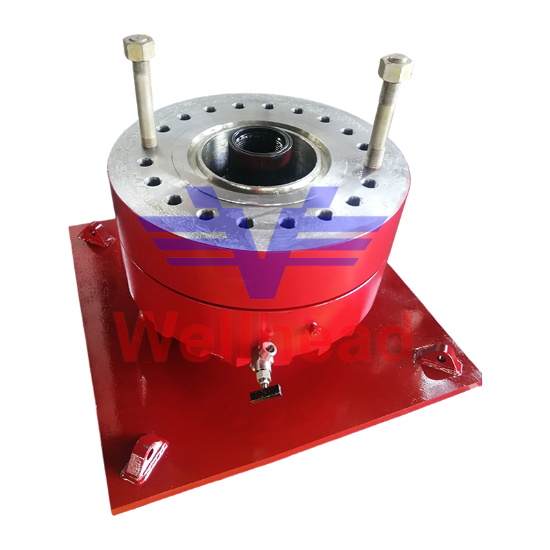 BOP Test Stump for Blowout Preventer Stack TestingBOP Test Stump for blowout preventer systems, providing high-pressure sealing and remote control in pressure-tested stacks with matched control units.View Product →
Where the Accumulator Meets the Stack
Specify the control unit and the stack hardware together, because the preventers themselves decide the usable volume you need.
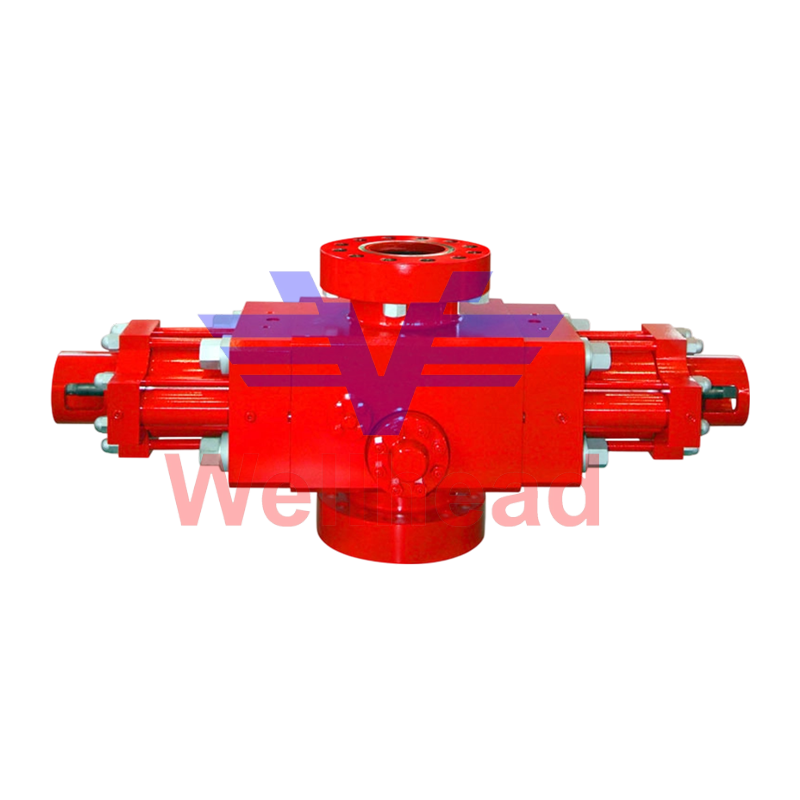
The biggest consumers of stored fluid are the annular preventer, which needs a large volume to seal around a range of pipe sizes, and the ram preventers, which must close and latch against well pressure. A two-ram stack with one annular is a common minimum; adding a shear ram or a second annular changes the usable-volume calculation, and therefore the bottle bank and pump size.
Matching pressure ratings, flange sizes and operator volumes to the control system at the specification stage avoids the usual field problems: slow closing, elements damaged by over-pressure, and panels that cannot operate every function on the drawing.
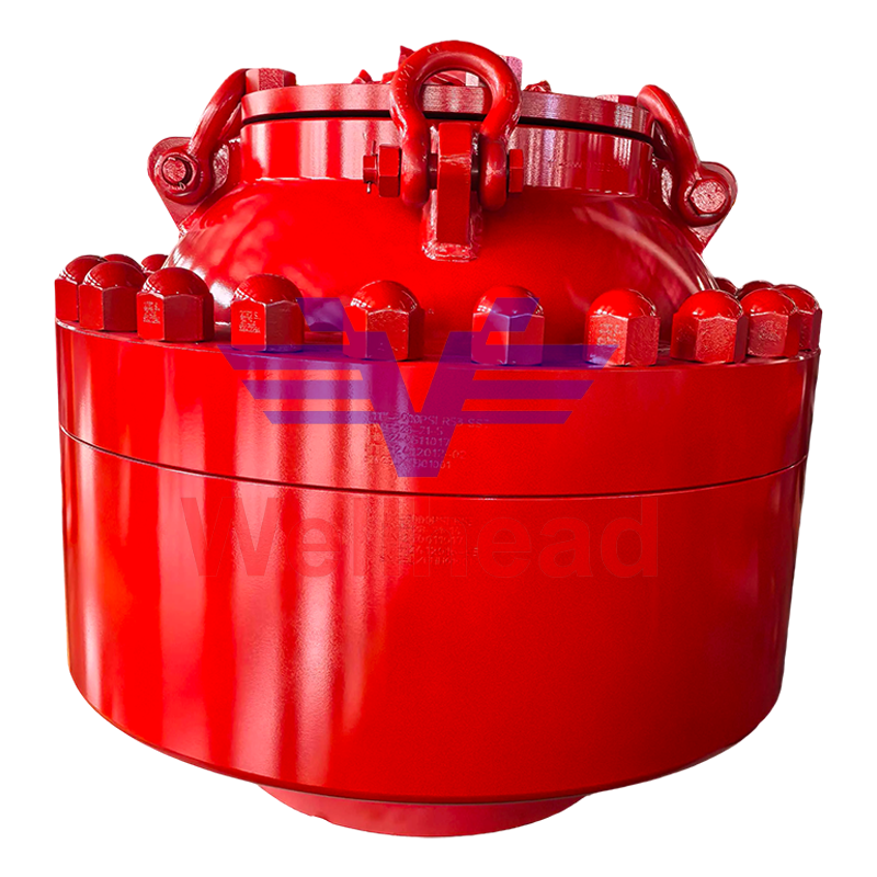 Annular BOP for Drilling Well Control and Emergency SealingAnnular BOP for drilling well control, offering annular sealing and quick response; choose with matched pressure ratings, flange sizes, and operator volumes.View Product →
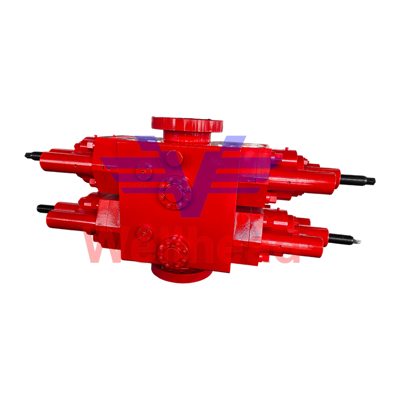 Double Ram BOP for API 16A Wellhead SealingDouble Ram BOP uses two rams for a sealing barrier; API 6A/NACE MR0175, with pressure, flange, and operator volumes matched to control systems.View Product →
FAQ
How much usable fluid does a BOP accumulator need?
Enough to operate every required emergency function in sequence and still stay at least 200 psi above nitrogen precharge, which is exactly what a draw-down test proves. Total bottle volume is not the answer.
What nitrogen precharge should I use?
On a 3,000 psi system, 1,000 psi at 70 °F is the common starting point, adjusted for the temperatures the unit will actually see. Verify it with the fluid side isolated and drained, and use dry nitrogen only.
How often should the accumulator be tested?
Daily pressure and fluid checks, with function and draw-down tests at intervals set by API Std 53, the operator's well programme and local regulation, not only after a failure.
Can one accumulator unit serve two rigs?
Generally no. Usable volume, hose runs and panel layout are designed around one stack and one rig layout, so a second stack usually means a larger bottle bank or a separate unit.
Buying an accumulator comes down to three verifiable things: a usable-volume figure proved by test, a precharge discipline that survives winter, and preventers that match the rated pressures on the drawing. Buyers who ask for all three, and confirm the manufacturing scope behind the API 16A and API 16C marks, rarely get surprised in the field.
The verification step is identical on new and recertified stacks, because every cavity is pressure-tested before the unit goes to work. That is why the BOP test stump belongs in the same conversation as the control unit.
 + 86-0515-88429333

 CONTACT US
