

 English
 русский
Wellhead integrity is the ability of the wellhead and Christmas tree assembly to contain wellbore pressure and fluids without leakage throughout the life of a well. In short, a wellhead with sound integrity holds its rated working pressure, keeps its metal-to-metal seals leak-free, and allows every valve, hanger, and actuator to perform as designed during drilling, completion, production, and intervention. When containment is lost, operators face immediate safety hazards, environmental exposure, and costly downtime.
Content
- What Is Wellhead Integrity and Why Does It Matter?
- Core Components That Support Wellhead Integrity
- Wellhead Integrity Testing: Standard Steps and Acceptance Criteria
- Common Wellhead Integrity Failure Modes
- How to Maintain Wellhead Integrity Over the Life of the Well
- Equipment Selection and Its Effect on Wellhead Integrity
- Wellhead Integrity FAQ
What Is Wellhead Integrity and Why Does It Matter?
Wellhead integrity is the total pressure-containment capability and mechanical soundness of the surface equipment stack connected to the wellbore. It covers three distinct dimensions:
- Pressure containment: no leakage through flange gaskets, ring-joint seals, hangers, or valve stems.
- Structural integrity: the stack can carry casing loads, thermal expansion, bending forces, and external impact without deformation.
- Functional integrity: every gate valve, choke, actuator, and pressure-monitoring device operates reliably when called on.
All three dimensions matter together. A well can hold pressure yet lose containment because a valve fails to close during a kick, or the structure can remain physically sound while a corroded seal develops a difficult-to-detect micro-leak. Wellhead integrity management therefore treats the entire assembly as one barrier system, from the casing head to the tree cap.
Core Components That Support Wellhead Integrity
Every component in the wellhead system plays a specific sealing or load-bearing role, and the weakest link defines the integrity of the whole stack.
| Component | Role in wellhead integrity |
|---|---|
| Casing head | Supports the surface casing string and provides the first sealing point between casing and wellhead. |
| Casing spools | Space out and support intermediate casing strings. |
| Tubing head | Supports the tubing string and isolates the tubing-casing annulus. |
| Tubing hanger | Holds the tubing and provides an energized seal that prevents annulus fluid migration. |
| Christmas tree | The main production control assembly containing master, wing, and swab valves. |
| Gate valves | Provide positive shutoff for production flow and well control operations. |
| Flanges and gaskets | Ring-joint and flange connections that preserve a leak-free pressure boundary between components. |
The casing head is the first pressure barrier between the wellbore and the surface, so its connection type, seal design, and load rating deserve particular attention. Understanding the basic structure of the casing head helps operators avoid mismatched flanges and underestimated load ratings during installation and later interventions.
In the production stage, the role of the wellhead assembly and X-mas tree in oil and gas production becomes the primary barrier between reservoir fluids and the environment. Master valves, wing valves, and chokes must be specified with the same rigor as the hangers and spools below them.
Wellhead Integrity Testing: Standard Steps and Acceptance Criteria
Wellhead integrity testing verifies that the wellhead and tree can contain pressure and that each barrier component functions as designed. The test sequence normally follows a clear progression:
- Pre-test inspection: verify flange alignment, bolt torque, seal condition, and test hookup.
- Low-pressure test: pressurize the system to the low test value, typically 200 to 500 psi, to confirm seal engagement.
- Stabilization period: hold the low pressure briefly to confirm it is stable before continuing.
- High-pressure test: raise pressure to the rated working pressure, usually 1.0 to 1.1 times the rated value.
- Holding period: monitor pressure for the required duration, normally 15 to 30 minutes, to detect decay.
- Valve function test: open and close each valve under pressure to verify operation and sealing.
- Documentation: record pressures, temperatures, hold durations, and any anomalies in the well file.
| Test stage | Typical value | Acceptance criterion |
|---|---|---|
| Low-pressure test | 200 to 500 psi | Hold for 5 minutes with no detectable pressure drop. |
| High-pressure test | Rated working pressure or 110 percent of rated | Hold for 15 to 30 minutes with stable pressure and no visible leak. |
| Valve function test | Full working pressure | Positive shutoff with no leakage across the closed valve. |
The acceptance principle is always the same: pressure must stabilize after each test stage, and any continuing decay indicates a leaking barrier that must be investigated before the well returns to service.
Common Wellhead Integrity Failure Modes
Most wellhead integrity failures develop gradually and can be detected before they become dangerous, provided the right inspection and monitoring routines are in place.
| Failure mode | Typical cause | What happens |
|---|---|---|
| Gasket or seal leak | Improper bolt torque, damaged ring gasket, or thermal cycling | Pressure and fluids escape through the flange connection. |
| Corrosion damage | H2S, CO2, chlorides, or produced brine attacking body and seal areas | Loss of wall thickness and deterioration of seal surfaces. |
| Erosion | Sand production or high-velocity flow through chokes and bends | Wall thinning and pitting in flow-wetted parts. |
| Hanger movement | Pressure and temperature fluctuations | Seals lose their initial energizing force and begin to leak. |
| Valve failure | Debris, wear, or actuator malfunction | The barrier can no longer close or seal when needed. |
| Casing or tubing movement | Thermal expansion or formation subsidence | External loads transferred to the wellhead exceed design limits. |
When any of these conditions is found, the standard response is to isolate the barrier, plan a repair or replacement, and re-run the integrity test before returning the well to service.
How to Maintain Wellhead Integrity Over the Life of the Well
Maintenance keeps a wellhead integral for decades, and a wellhead integrity management system ties the required activities together. Recommended practices include:
- Schedule visual and torque inspections of flanges and fasteners at defined intervals.
- Monitor corrosion using coupons, corrosion loops, or ultrasonic thickness measurements on pressure bodies.
- Exercise production and wing valves regularly to prevent sticking.
- Track temperature and pressure cycles to identify abnormal loads on hangers and seals.
- Keep a documented testing history for every barrier component.
- Consolidate inspection, testing, and repair records in a wellhead integrity management system.
Operators who apply these practices consistently see fewer leaks, lower repair costs, and fewer regulatory findings over the life of the well.
Equipment Selection and Its Effect on Wellhead Integrity
Equipment selection determines the level of wellhead integrity that can be achieved before the well is even completed. Three decisions matter most: rated working pressure, material class for the expected corrosive service, and valve type at each barrier position.
For production service, the starting point is a certified wellhead and Christmas tree assembly rated for the maximum expected surface pressure and temperature. Material class must be specified against the full composition of produced fluids, not just the initial reservoir analysis.
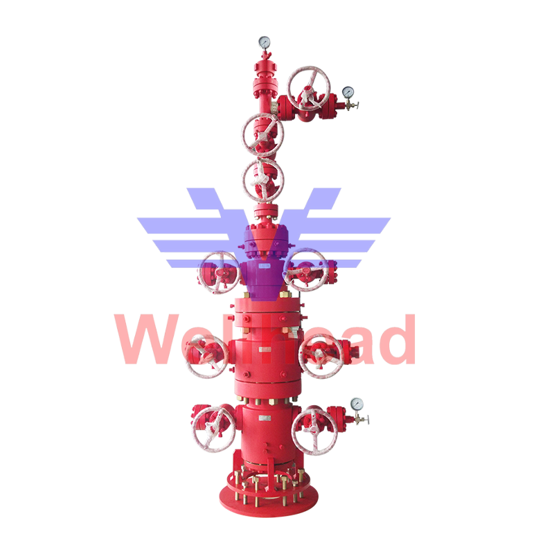 Wellhead and X-mas Tree Assy Suppliers, Custom Wellhead and X-mas Tree Assy ComJiangsu Wellhead Drilling Equipment Co., LTD is China Wellhead and X-mas Tree Assy suppliers and Wellhead and X-mas Tree Assy company, ...View Product →
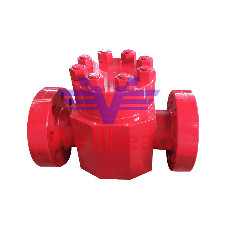
For isolation and shutoff duties, an API 6A gate valve is the most widely used barrier element because its straight-through bore and metal-to-metal sealing provide reliable shutoff with minimal pressure drop. Compared with ball valves, gate valves expose less of the sealing surface directly to flow erosion, which is why they remain the default choice for master and wing valves in wellhead service.
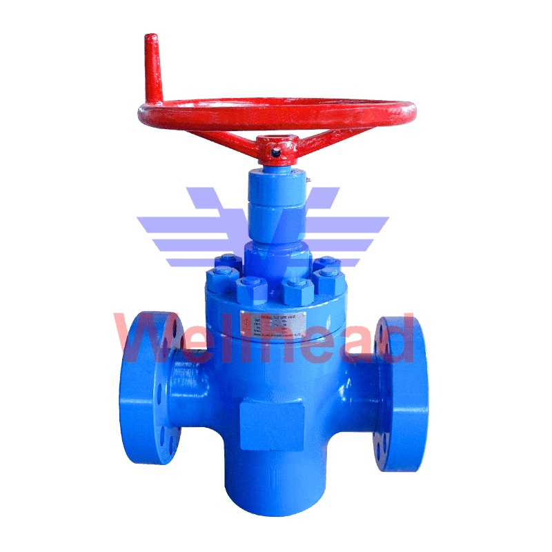 API 6A FL Flat Gate Valve Suppliers, Custom API 6A FL Flat Gate Valve Company - Jiangsu Wellhead Drilling Equipment Co., LTD is China API 6A FL Flat Gate Valve suppliers and API 6A FL Flat Gate Valve company, We speci...View Product →
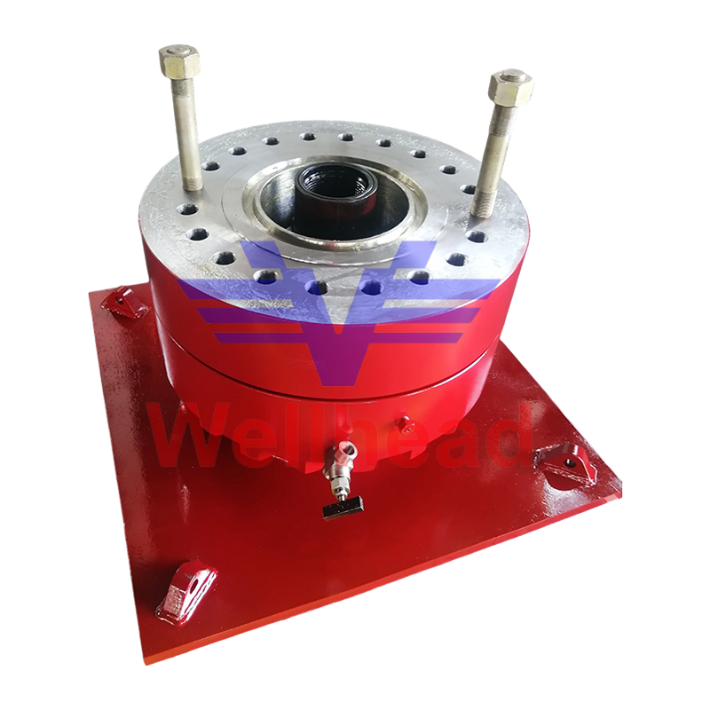
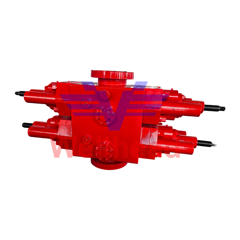
During drilling and workover phases, well-control equipment above the wellhead is part of the same barrier envelope, and an annular blowout preventer offers the fastest sealing response around drill pipe, casing, and wireline, making it a critical element of a complete integrity strategy.
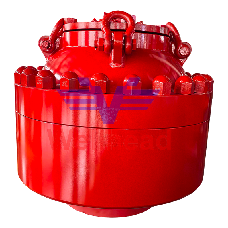 Annular BOP Suppliers, Custom Annular BOP Company - Jiangsu Wellhead Drilling EqJiangsu Wellhead Drilling Equipment Co., LTD is China Annular BOP suppliers and Annular BOP company, We specialize in production custom A...View Product →
| Material class | Typical service | Example application |
|---|---|---|
| AA / BB | Sweet, non-corrosive service | Standard production wellheads |
| CC / DD | Mild sour service with low H2S | Wells with trace H2S content |
| EE / FF | Severe sour or high-chloride service | High-H2S wells and high-salinity brine production |
Selecting equipment that matches the real service envelope reduces the frequency of failed seals, valve repairs, and unplanned integrity interventions over the life of the asset.
Wellhead Integrity FAQ
What is wellhead integrity testing?
Wellhead integrity testing verifies that the wellhead, tree, and related barriers hold pressure without leakage and that their valves operate correctly, using low-pressure and high-pressure cycles plus functional valve tests.
How often should a wellhead integrity test be performed?
Frequency depends on regulatory requirements, well type, and risk profile. Many operators test critical barriers at least once per year and after any intervention, with more frequent tests for high-risk wells or wells with a history of seal problems.
What causes wellhead seal failure?
The most common causes are improper fastener torque, damaged sealing surfaces, thermal cycling that relaxes the seal load, and corrosion or erosion of the seal area.
What is the difference between low-pressure and high-pressure testing?
A low-pressure test confirms that seals are engaged and lightly energized, while a high-pressure test verifies the system can contain its rated working pressure. Both are needed because some leaks appear only at low pressure, while pressure-dependent leaks appear at high pressure.
 + 86-0515-88429333


 CONTACT US
